E-Cell is a high-tech enterprise specializing in the development and production of EDI stacks. 

For many years, operators of pure water production systems have been seeking a technology to replace mixed-bed ion exchange for final demineralization. The operating costs, as well as the complexity and risks associated with acid and caustic regeneration, were sources of frustration for these operators. EDI has established itself as an innovative alternative by reducing operating costs, improving site environmental, health, and safety risk profiles, and producing a continuous, steady supply of pure and ultrapure water.

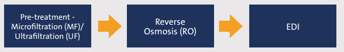
Production of pure water has evolved from conventional pretreatment with multiple stages of ion exchange in initial and final demineralization to the following membrane-based operations, including EDI, that are now considered to be best practice by many customers around the world: 

EDI utilizes both traditional ion-exchange resins and ion-exchange membranes to remove contaminants, including uncharged or lightly charged species in the feed water, such as silica and boron. The biggest advantage is that EDI technology uses direct current to drive contaminants out of the feed water and through the ion-exchange membranes into the concentrate channels.

Direct current also splits water into hydrogen and hydroxyl ions, which act as continuous regenerating agents, preventing contaminants from accumulating on the ion-exchange resin. Therefore, EDI can continuously and predictably produce high-purity and ultrapure water with quality equal to or better than that of mixed-bed ion exchange.

E-Cell* Electrodeionization (EDI) by Veolia

E-Cell distributor

DeionX is the distributor for Veolia E-Cell products. Our equipment and expertise are used worldwide across various industries, including power, pharmaceutical, and food, to produce ultrapure process water and research and laboratory water. In contexts where the highest-grade purified water is imperative, we can deliver Type 1 water that meets the most stringent standards for critical applications. As a worldwide respected ‘Service Provider’, we distribute a variety of Ultrapure Water-related modules, including spares and consumables, directly from our European store based in the Netherlands, like:

Electrodeionisation (EDI) stacks of E-Cell
DC Power Supplies for (C)EDI

Our distributor DeionX

  • Best price quality ratio
  • Short lead time
  • Worldwide 24/7/365 support

Product groups

Our EDI stacks.

  • E-Cell Stacks
  • Spareparts

E-Cell Key Features and Benefits

  • Counter-Current Operation: 

    • Minimizes scaling, even with higher feed water hardness.

  • NO STACK BOLD TIGHTING

    • Benefits less external maintenance required & less potential for stack leakage/weeping

  • Efficiency & Performance: 

    • Provides high-purity water while consuming low energy.

  • Compact Footprint:

    • Smaller, lower-height design compared to conventional ion exchange systems.

DeionX can offer you:

  • EDI stacks
  • DC Power Supplies and controllers for (C)EDI
  • Connectors (various type of materials)
  • Earthing rods
  • Complete systems
  • Technical support

Frequently asked questions about E-Cell

What is electrodeionisation (EDI)?

EDI is a chemical-free process for producing Ultra-Pure Water by removing ions from Reverse Osmosis product water using an electric potential. 

Electrodionisation is a logical evolution of conventional ion-exchange technology. Equal to conventional ion exchange, ion exchange resins exchange cations and anions from the feedwater for hydrogen and hydroxyl ions, producing high-purity demineralized water. The key operational difference and a main feature of EDI is that resins are continuously regenerated without the use of chemicals. This electrochemical process is achieved by ion-conducting membranes under a DC current. Hydrogen and hydroxyl ions are produced by the water dissociation reaction (water splitting) and continuously regenerate the resins without adding any chemical reagents.

H2O ↔ H+ + OH-

The electric potential at each end of the module drives water splitting and, at the same time, causes ions to migrate to the selectively permeable membrane, where they pass into the next concentrate chamber. Once the ions are trapped in the concentrate compartment, they are carried away by the concentrate stream.

What are the main reasons of malfunctioning EDI systems?

EDI feedwater must be purely RO product water and must be prevented from recontamination!

Open storage tanks, degasifiers, and softeners between RO and EDI are often responsible for EDI fouling. Each filtration step between RO and EDI that might introduce new particles into the EDI feed water will require an additional 1 µm absolute pre-filtration step directly before the EDI. Air intake filters with a 0,2 µm rating are required on all open connections of storage tanks feeding the EDI system.  


Physical Contamination:

  • Plastic shavings from piping installation,
  • Metal shavings from construction work,
  • Dirt, dust, pollen, construction or welding debris,
  • Resin beads/fines.


Chemical contamination:

  • Oxidants, such as chlorine,
  • Polyvalent cations, such as iron and manganese.
What are the limitations of E-Cell Stacks?

Limits for Iontech modules:


Minimum limits

Maximum limits

Stack

Part

Dilute

Conc.

Electrode

Dilute

Conc.

Feed

DC power

Type

number

Flow

Flow

Flow

Flow

Flow

Pressure

Voltage

Current

MK-3MiniHT

3044124

0,57 m3/h

30 l/h

57 l/h

1,52 m3/h

220 l/h

6.9 bar

200 VDC

5,2 Amp

MK-3PharmHT

3041772

1,6 m3/h

90 l/h

57 l/h

4,54 m3/h

600 l/h

6.9 bar

300 VDC

5,2 Amp

MK-3

3018626

1,6 m3/h

90 l/h

57 l/h

4,54 m3/h

600 l/h

6.9 bar

300 VDC

5,2 Amp

MK-5

3057694

2,3 m3/h

130 l/h

57 l/h

6,4 m3/h

800 l/h

6.9 bar

400 VDC

5,2 Amp

MK-9

3221110

4,2 m3/h

130 l/h

57 l/h

7,8 m3/h

800 l/h

6.9 bar

400 VDC

5,2 Amp

MK-5D

3222128

4,6 m3/h

260 l/h

114 l/h

15,6 m3/h

1600 l/h

6.9 bar

400 VDC

5,2 Amp

MK-9D

3222287

8,4 m3/h

260 l/h

114 l/h

20 m3/h

1600 l/h

6.9 bar

400 VDC

5,2 Amp

The minimum required feed pressure depends on the operating choice.

  • Counter-Current 4,1 bar

  • Co-Current 3,1 bar 

Pre-treatment is crucial for the functionality of the EDI process. Direct-coupled Reverse Osmosis product water quality is required as feedwater for EDI.  


E-Cell operating Limitation (RO permeate or better)


MK-3MiniHT

MK-3PharmHT

MK-3

3X now MK-5

MK-5D

MK-7 now MK-9

MK-9D


FEEDWATER


TEA - Total Exchangeable Anions (as CaCO3)

25

25

13

ppm

Conductivity

< 43

< 43

< 22

µS/cm

pH range

4 - 11

4 - 11

4 - 11


Temperature

5 - 40

5 - 40

5 - 40

0C

Total Hardness (as CaCO3)

< 1,0

< 1,0

< 1,0

ppm

Silica (SiO2)

< 1,0

< 1,0

< 1,0

ppm

Total Organic Carbon (TOC)

< 0,5

< 0,5

< 0,5

Ppm

Turbidity

< 1,0

< 1,0

< 1,0

NTU

Color

< 5,0

< 5,0

< 5,0

APHA

Chlorine

< 0,05

< 0,05

< 0,05

ppm

Fe, Mn, H2S

< 0,01

< 0,01

< 0,01

ppm

Oxidant

Not detected

Not detected

Not detected

ppm

Oil and grease 

Not detected

Not detected

Not detected

ppm

SDI15

< 1,0

< 1,0

< 1,0

ppm


Product Water Quality

Resistivity

>10

>16

>16

MΩ.cm


Operating Parameters

Recovery

Up to 96

Up to 96

Up to 97

%

Dilute inlet/outlet pressure drop

1,4 – 2,8

1,4 – 2,8

2,4 – 3,4

bar

Minimum pressure difference between 

dilute outlet and concentrate inlet

0,34

0,34

0,34

bar


Stack

MK-3MiniHT

MK-3PharmHT

MK-3

MK-5

MK-9

MK-5D

MK-9D


Nominal

flow

1,14

3,4

3,4

5,0

8,0

10,0

16,0

m3/h

5,0

15,0

15,0

22,0

35,2

44,0

70,4

gpm

Shipping weight

57

100

100

165

165

290

290

Kg

126

220

220

364

364

639

639

lbs

Dimensions

WxHxD

30x61x29

30x61x54

30x61x54

30x61x74

30x61x74

40x61x76

40x61x76

Cm

12x24x12

12x24x22

12x24x22

12x24x29

12x24x29

19x24x30

19x24x30

inch


Actual feed water quality specifications and performance may vary depending on flow rate through each stack and site conditions. Entries here based on nominal flow. Reference fact sheets and Winflows projection software to verify actual performance.


Is bold tighting required?

Stack bolt tightening is not required for E-Cell stacks. Which benefits: less external maintenance required & less potential for stack leakage/weeping. 

What does counter-current and co-current mean?

E-Cell systems typically operate in a once-through, counter-current flow configuration. Standard Veolia E-Cell systems are designed for once-through, counter- current flow. The Dilute and Concentrate flows in the stack run in opposite directions. The Dilute Inlet is at the bottom of the E-Cell stacks (the Electrode stream is fed internally from the Dilute Inlet). The Dilute Outlet is at the top. The electrode outlet is at the top of the stacks. The Concentrate Inlet is at the top and Concentrate Outlet (Bleed) at the bottom of the stacks. An advantage of counter-current flow is greater tolerance for feed water hardness than co-current flow. Hardness scaling occurs more slowly, so cleaning to remove it is required less often at the same level of feedwater hardness and recovery with counter-current flow than with co-current flow. With counter-current flow, the feed water may contain up to 1 ppm of CaCO3 hardness.  In counter-current flow, the minimum system feed pressure at nominal E-Cell stack flow is 4.1 bar (60 psi). The feed pressure requirement may be higher depending on downstream conditions. Once-through, co-current flow, where Concentrate  Inlet is at the bottom of the  E-Cell stack and Outlet (Bleed) at the top, is also possible, but may be applied only where the feed water contains <0.10 ppm as CaCO3 of hardness. In co-current flow, the minimum system feed pressure at nominal E-Cell stack flow is 3.1 bar (45 psi). The feed pressure requirement may be higher depending on downstream conditions.  The lower typical feed pressure requirement is an advantage of co-current over counter-current flow.  

What is the difference between FCE and TEA, and how can I calculate them?

You need to know the following parameters for calculation:
Conductivity in µS/cm, 
CO2 in ppm,
SiO2 in ppm.
FCE = Feedwater Conductivity Equivalent = Conductivity + CO2 * 2,66 + SiO2 * 1,94 = ≤ 40 µS/cm
Example calculation FCE:
Conductivity  = 15 µS/cm = 15,00
CO2  = 7,5 ppm * 2,66 = 19,95
SiO2 = 0,5 ppm * 1,94 =   0,97  +
 --------------------
 35,92  µS/cm


TEA = Total Exchangeable Anions = CO2 * 2 + Conductivity * ⅔ = ≤ 25 ppm as CaCO3
Example calculation TEA:
Conductivity  = 15 µS/cm * 2/3 = 10,00
CO2  = 7,5 ppm * 2 = 15,00
 --------------------
 25,00  ppm as CaC03


Both numbers give you basically the same information. 25 ppm TEA as CaCO3 compares to ~38 µS/cm FCE. As silica is not part of the TEA, and 1 ppm SiO2 is the maximum allowed, compared to 1,94 µS/cm, it comes approx. to the same 40 µS/cm FCE as the maximum allowable load for EDI modules.  

What happens if the FCE or TEA is to high?

When the FCE or TEA is too high, you’re loading more ions than the EDI module can extract. When the module is well regenerated, you might not notice this if it occurs briefly. However, the resins in the EDI will gradually become exhausted, leading to poor product quality. A high CO2 load will almost directly result in poor product quality.
As long as the high load is caused by non-scaling ions, it will not damage the module. Once the feedwater conductivity equivalent is back within the specification limits, the resins will automatically regenerate, and the module will restore itself.

Why is the feedwater limit for hardness and silica so low?

Usually, EDI systems operate at high recoveries of 90 to 95%, resulting in concentration factors of 10 to 20 times the incoming ions. 
All positive ions move towards the cathode through the cation-selective membrane and can’t move through the next anion-selective membrane. 

Along the Cation membrane, inside the concentrate chambers, H+ ions are 2 to 9 times more concentrated, creating low-pH spots along the Cation membrane surface.

All negative ions move to the anode through the anion-selective membrane and cannot move through the next cation-selective membrane. At the Anion membrane, inside the concentrate chambers, the OH- ions are 2 to 9 times more concentrated, creating high-pH spots along the Anion membrane surface.  

H+ and OH- ions concentrate 2 to 9 times, creating low- and high-pH areas at the membrane surface within the concentrate chamber, where they can readily promote hardness and/or silica scaling. 


The maximum allowable recovery depends on the concentration of hardness and silica in the feedwater.

Total Hardness (as CaCO3)

≤ 0,2

0,2 – 1,0

ppm as CaCO3

Silica (SiO2)

≤ 0,5

0,5 – 1,0

ppm as SiO2

Allowable Recovery for all modules

95

90

%


Why is the feedwater limit for iron,manganese and sulfides so low?

Iron, Manganese, and Sulphide are tightly held by the resins and may oxidize and precipitate within the resin before they can be transferred to the concentrated waste stream. This might cause internal problems in any EDI module.

What is the free chlorine tolerance for EDI modules

The tolerance for free chlorine (Cl2) is very low, like below 0,05 ppm. Basically, EDI modules are even more sensitive to chlorine than most RO Thin Film Composite (TFC) membranes. Free chlorine can damage an EDI stack before you see any signs in the downstream RO system. 
As for all oxidants, the ideal concentration is as low as zero, not detectable!

Why is the feedwater limit for TOC

The organics that define TOC (Total Organic Carbon) will cause resin and membrane fouling. This will lead to inefficient ion transport and removal. TOC fouling should be limited as much as possible.

What are the pH limits for E-Cell EDI modules?

During operation, the feedwater pH should be between 4 and 11.
During a periodic cleaning, a pH of 1 for acid cleaning and 12 for caustic cleaning is allowed.

What are the temperature limits for E-Cell stacks?

The water temperature entering an E-Cell EDI stack should be between 5°C and 40 °C. When the temperature drops below 5 °C, the electrical resistance of any (C)EDI module or E-Cell stack can reach a critical point, requiring a higher DC voltage. Below 5 0C, you might reach the power supply voltage limit, and performance will decline.

What is the inlet pressure limitation for an E-cell EDI module?

The maximum inlet pressure is 6,9 bar (100 psi).

Electrodeionization (EDI) versus Mixed Bed (MB) deionization?
 

Electrodeionisation

Mix Bed

Type of process

Continuous, self-regenerating

Batch, Exhausting 

Hydraulic control

Quite simple

Quite complex

Operational cost

Low

High

Maintenance cost

Low

High

Personal risk operators

Low

High, due to the use of chemicals

Environmental

Friendly

Chemical polluting

Downtime

Not applicable

During the regeneration process

Physical contamination

High sensitive

Low sensitive

Footprint

Relative small

Relative large

From which material are the Anode and Cathode made?

The Anode plate is made of coated titanium (IrOx/TiO2 on Ti), while the Cathode is made of Stainless Steel.

Questions about our services?

You can read how we handle your personal data in our Privacy policy

Producing high quality and efficient Continuous De-lonisation stacks.